HAMU - Rack Extensions
Rack Extensions for Propellerheads Reason
WELCOME TO THE HAMU WEB SITE OF
RACK EXTENSIONS FOR PROPELLERHEAD REASON
We love patch cables. The back plane of Reason is the place for creativity and magic. Our Rack Extensions is our humble contribution to empower all experimentalists with more flexibility and tools for the exploration of Sounds!
Mesher4B Mesher4K Mesher8B Mesher8K
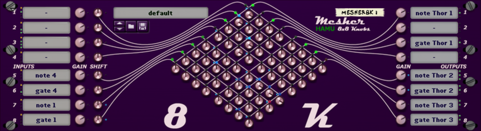
The Mesher devices combine CV splitting and merging, letting you control all your CV connections from front panel buttons or knobs.
By combining splitters and mergers into a switch board - or a mixer - you have immediate access to rework your connections up front.
The Mesher units enable you to easily combine your CV signals any way you please, in a highly creative process. Whenever you find an interesting setting you can save it as a new patch, so you can bring it back up later. Swapping patches is usually so quick that in a live situation, you can change your settings whenever you feel like it - mid song.
And a generous amount of lamps will indicate to you what's going on there, back in the cables.
Mesher comes in four flavours; 4 by 4 (four inputs and four outputs) and 8 by 8, and Button switches or Knobs for the connection nodes in the mesh.
BASIC FUNCTIONALITY
The Mesher devices combine CV splitting and merging, letting you control all your CV connections from front panel buttons or knobs.
SWITCH BOARDS AND MIXERS FOR CONTROL VOLTAGES
The Meshers are designed let you handle and experiment with your CV cables from the front panel. By having as many outputs as inputs, and the freedom to connect many to many, 'anything ' is possible.
With the buttons versions you will be able to quickly switch all kind off CV effects on and off. E.g. change betweeen CV sources, merge different kinds of preset LFO waves. note sources and so on. Switching can be manually or from modulation CV.
The knobs versions on the other hand, are more useful when you want to gradually change CV signal, by turning knobs or by applying modulation signals to the knobs' CV sockets.
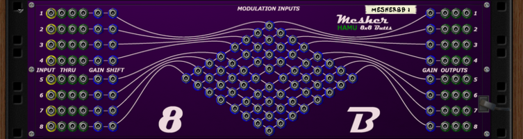
MESHER PARTS AND DETAILS
INPUT CONTROL VOLTAGE LINES
CV INPUT SOCKETS
There are four or eight CV input sockets to each Mesher.
On the front, a yellow small LED indicates where an input cable is connected.
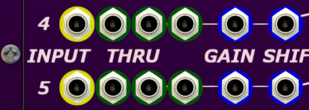
THRU OUTPUT SOCKETS
Just beside each input socket there are three ‘thru’ output sockets, to facilitate easy insert of the device in an existing CV signal path, and to offer more usage flexibility.
The yellow input cable LED, is flanked by two green ‘cable connected’ LED indicator for the thru sockets.
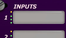
TEXT TAG DISPLAY
Each input line has its text tag display, to help the user identify the signal and aid the memory of intended use for the settings.
The tags will be saved and restored with patch files.
LEVEL QUANTIZATION
There is an additional use of the tag texts: If they start with ‘n’ or ‘g’ the signal will be quantized regarding voltage level, to align it with the midi protocol specification of 128 levels (0 – 127).
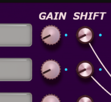
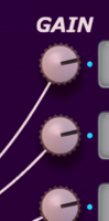
INPUT GAIN
From the socket, the signal goes to a gain module. The gain factor is defined by the knob setting between -2.0 and +2.0, plus any signal level on the gain modulation socket. The input signal is multiplied with the gain factor.
A blue LED indicates a modulation cable is attached.
The gain knobs settings will be saved and restored with patch files.
INPUT SHIFT
After gain there is a shift module, where a fixed level is added to the signal. The knob can add anything from -1.0V to +1.0V, and any shift modulation is added too.
A blue LED indicator shows when a modulation cable is attached.
The shift knobs settings will be saved and restored with patch files.
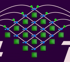
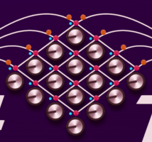
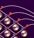
INPUT SIGNALS TO MESH
From the shift module, the signal goes to the mesh inputs where the level is indicated by a LED lamp. These lamps have two colors, orange for negative levels and green for positive, and the brightness indicates the strength of the signal (distance from 0).
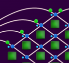
THE MESH NODES
There are 16 (4x4) or 64 (8x8) mesh nodes to a Mesher, either all knobs or all buttons. The knobs version is intended for mixing input signals with different amounts to each output, while the buttons version is best suited for distinct switching between different input signals.
For both knobs and buttons versions, there are two LED indicators for each mesh node:
A larger dual color LED lamp shows the signal added to the output, from red @-1V to blue @+1V.
A smaller blue cable indicator is lit when a modulation cable is attached.
MESH KNOBS
A knob multiplies the mesh input signal by a factor between -1 and +1, giving before adding the result to the output of the node.
If a modulation signal is attached, its level will be added to the knob factor setting and the sum is multiplied to the mesh input.
Thus, the contribution from a mesh knob node is any level as calculated from signals and knobs.
The knob setting will be saved and restored with patch files.
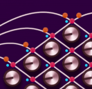
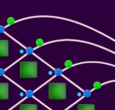
MESH BUTTONS
A button multiplies the mesh input signal by 0 or 1, open or closed connection.
If a modulation signal is attached it will affect the switch only when the button is lit, and will then close (connect) the switch only when the modulation voltage is higher than 0.01V (to cover for noise).
Thus, the contribution from a mesh button node is either 0 or equal to the mesh input.
The button status will be saved and restored with patch files.
OUTPUT CONTROL VOLTAGE LINES
There are four or eight CV outputs to each Mesher, always same number as inputs.
MESH OUTPUT SIGNALS
All contributions from mesh nodes connected to an output line are summed up to a mesh output level. Just as on the mesh input side, this level is indicated by a dual color lamp of orange to green. The lamps brightness stop increasing at -1V and +1V, while the signal can be higher or lower than this.
Please notice that the brightness of these lamps relates to the output level after the output Gain, since this is the interesting value. A bit misleading lamp position maybe.
OUTPUT GAIN
From the mesh, the output signal goes to an output gain module. The gain factor is defined by the knob setting between -2.0 and +2.0, plus any signal level on the gain modulation socket. The mesh output signal is multiplied with the gain factor.
A blue LED indicates when a modulation cable is attached.
The output gain knobs settings will be saved and restored with patch files.
TEXT TAG DISPLAY
Each output line has its text tag display, to help the user identify the signal and aid the memory of intended use for the settings.
The tags will be saved and restored with patch files.
LEVEL QUANTIZATION
There is an additional use of the output tag texts: If they start with ‘n’ or ‘g’ the output signal will be quantized regarding voltage level, to align it with the midi protocol specification of 128 levels (0 – 127, divided by 127). A side effect of this is that the output is clamped between 0.0V and +1.0V.

OUTPUT SOCKETS
There are three output sockets for each output line, to reduce the risk of running out of outputs.
Finally there is of course a green ‘cable connected’ LED indicator for each of the two output sockets.
COMBINATOR PATCHES & DEMO VIDEOS
Malström Pad Playground
A Malström pad sound which can be rhythmically modulated by toggling on/off different sound sources.
Kindly provided by Jörg Künnemeyer, 'midid50'. Thank you Jörg.
This is a really nice school example patch for working with buttons of a Mesher to connect different modulations sources to different sound parameters. You run the pattern devices, to provide a number of CV sources to the Mesher8B, and then you can play some slow chord progression and toggle through the Mesher-buttons. This is a typical setup where a buttons Mesher is easier to use than one with knobs.
CV sources:
Ch1-4 are gate signals from Redrum Ch1-4 with different rhythms in, which can be stacked.
Ch5 is the Envelope Follower of Scream4, which is fed by a Dr.OctoRex and a rhythmical soundpattern. I duplicated it into the mixer, so you can also listen to it, if wanted.
Ch6-8 are Malström Outs: FilterEnv, Mod A, Mod B.
CV Destinations:
The Malström Shift, Index and Filter and finally Pitch, which is very sensitive, and good for "checking" the modulation CV.
A Percussion Combinator
Intricately floating rythmic patterns will flow from this patch.
Provided to you by Aaron Bergman, 'ravasb'. Thanks Aaron.
This patch includes 4 Matrixes, a couple of Meshers, 3 Thors and an Alligator, and all you have to do is 'run' the devices.
Connections within are a bit tricky to follow, but will show you how you can use the 'mesh' modulation inputs to automate the mixing and routing of CV sources.
This is a more complex setup including not only MidiTappers, but also several Meshers, Minglers and a ModStepper (FREE!).
Here's how to use it:
The midi keyboard is always set to play C0 at the low end.
Octave is controlled with C0 as tap key; Single tap will move up one octave, double tap will move down and press moves to middle (C4).
Harmonics are controlled with C#0; Single tap adds/removes a higher note, while double tap adds/removes a lower note. The level of the harmonics are controlled from the velocity of the same tap key C#0.
Above C#0 the keyboard is used for playing.
The tradeoff of this setup is that - due to the nature of sequencer CV - all played notes are sustained until all keys are released.
Please check out the video to see how it works!
VIDEO OF SETUP
Says Håkan:
What I've tried to accomplish is to have a basic home and light travel 'live' setup where I only use one midi keyboard.
The keyboard I use doesn't have a split, so my aim here was to create a setup where I can change octaves from the midi keyboard, with a tap key, while still keeping all tap keys in place independent of octave.
As an example of things I like to have available from tap keys, I also added harmonics with a Mesher, which can be turned on and off with a tap key.
A Christmas Tree for Your Reason Rack
Time to decorate your rack?
Here's the combinator patch of the season for you who have Mesher8B!